View bucket positions in Client (Bucket Positions tab)
Bucket traces can be imported into XECUTE and visualised in the 3D Scene via a Bucket Positions Data Feed In configured in XECUTE Config. The Bucket position points can then be used to trim the face positions of activity areas. See Data Feed In.
In Client, the Bucket Positions tab has filter and sort controls to manage the visible bucket positions. The filtered set will be visible, and only those bucket positions are used to trim the activity areas.
To trim an activity area or areas by the bucket positions, make the bucket positions visible in the Bucket Positions tab then follow the steps outlined in Trim face position with bucket data below
Tab menu
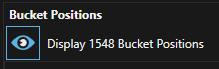
Click the eye icon to toggle the visibility of the bucket position points.
Trim face position with bucket data
Bucket position data can be used to update face positions for activities that move material.
- Filter the bucket positions in the grid as required (typically based on the Resource field) and click the Eye icon in the menu to make them visible.
- Select the Activity Area, then right-click the area to display the radial menu.
- Select the Trim with Bucket Positions from the radial menu to open the Trim Optionsdialog.
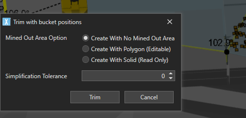
Create with no mined out area
This option allows you to edit the trimmed shape of the activity area after it has been trimmed by the bucket positions. The trim line is taken as the edge of the bucket extents with a small buffer. No mined out area is created.
Create with polygon
This option allows you to edit the trimmed shape of the activity area after it has been trimmed by the bucket extents. The trim line is taken as the edge of the bucket extents with a small buffer.
Create with solid
This will use the bucket position's Z extents to create a surface which will be the floor of a mined out activity area. The resulting solid is imported as a mined out activity area solid, which may be more accurate to the data, but the resulting activity area is not editable.
Any bucket positions where the lower Z value is below the activity area mining level will not be used in the trim operation.
Simplification tolerance
The polygon created with Create with Polygon and Create with No Mined Out Area options can be simplified to remove unnecessary vertices.
The default value is 0, which means no simplification is applied.
The tolerance represents the perpendicular distance to a line segment, such that any vertices within this distance will be removed.
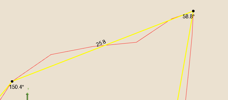
The images below show two tolerance settings.
-
Red - Tolerance = 0.
-
Yellow - Tolerance = 1.1.
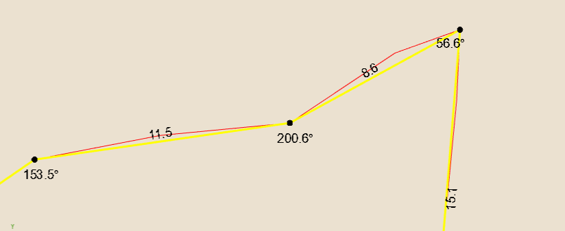
-
Red - Tolerance = 0.
-
Yellow - Tolerance = 2